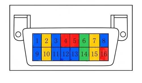
If you've ever removed an OBD connector and looked at the back, you may have noticed something interesting: although all 16 pin positions are present, only five or six of them may actually have wires attached.
This isn't cost-cutting-it's by design.
The SAE J1962 standard defines only the physical configuration of the OBD connector: a 16-pin trapezoidal connector that prevents incorrect insertion. However, it does not require every pin to be populated. Which pins are connected-and which remain unused-depends entirely on the vehicle's communication protocol and the manufacturer's implementation.
Think of it like a household electrical outlet. The standard defines the shape and orientation of the socket, but what each wire carries depends on how the building is wired.
So, if you find that a vehicle's OBD connector only has metal terminals on Pins 4, 5, 6, 14, and 16, there's no need to be surprised. In fact, this usually indicates that the vehicle uses the modern CAN bus communication protocol.
Understanding the 16 Pins by Function
To make things easier to understand, let's group the pins by their functions.
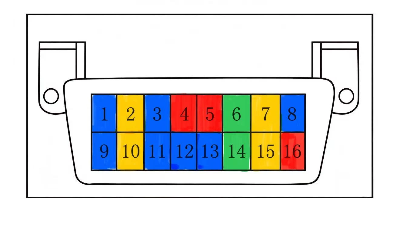
🔴 Power Pins (Red)
Pin 16 - Battery Positive (+12V Constant Power)
This is the OBD connector's primary power source.
Pin 16 is connected directly to the vehicle's battery positive terminal. Even when the engine is off, it typically provides a constant 12-volt supply, allowing a scan tool to power up as soon as it is plugged in.
Pin 4 - Chassis Ground
Pin 4 connects to the vehicle's metal chassis and is electrically connected to the battery's negative terminal.
Together with Pin 16, it forms the main power circuit for diagnostic equipment.
Pin 5 - Signal Ground
Pin 5 provides the reference ground for sensitive electronic control units (ECUs) and diagnostic communications.
Although both Pins 4 and 5 are grounds, they serve different purposes:
Pin 4 (Chassis Ground): Carries higher current through the vehicle body.
Pin 5 (Signal Ground): Provides a clean electrical reference for sensitive electronic signals.
They are not interchangeable, as separating power and signal grounds helps reduce electrical noise and improves communication reliability.
💡 Practical Tip
If your scan tool won't power on, the problem is often related to the power supply or grounding.
Start by checking:
Whether Pin 16 has approximately 12 V.
Whether Pins 4 and 5 have good continuity to the vehicle chassis.
These simple tests can quickly narrow down the problem.
🟢 CAN Bus Pins (Green) - The Backbone of Modern Vehicles
Pin 6 - CAN High (CAN-H)
Pin 14 - CAN Low (CAN-L)
These two pins form today's primary diagnostic communication channel.
Since 2008, major markets such as the United States and the European Union have required newly introduced vehicles to support CAN-based diagnostics in accordance with ISO 15765-4.
Pins 6 and 14 work as a differential pair, carrying high-speed communication between diagnostic equipment and the vehicle's control modules.
Information transmitted over these lines includes:
Engine speed (RPM)
Vehicle speed
Coolant temperature
Instantaneous fuel consumption
And many other real-time operating parameters
Today, more than 90% of vehicles on the road communicate through the CAN bus.
💡 Practical Tip
The resistance measured between Pins 6 and 14 should normally be about 60 Ω with the ignition off.
A significantly different reading usually indicates an open circuit or short circuit somewhere on the CAN network, which can prevent successful communication.
🟡 Legacy Communication Pins (Yellow) - The Retiring Veterans
Pins 2 & 10 - SAE J1850 Bus
This protocol was widely used on American vehicles, particularly Ford and General Motors, throughout the 1990s and early 2000s.
Pin 2: Bus+
Pin 10: Bus–
As CAN became the industry standard, J1850 gradually disappeared.
Pin 7 - K-Line (ISO 9141-2)
Pin 15 - L-Line (ISO 9141-2)
Before CAN became universal, K-Line was commonly used on European and Japanese vehicles, including brands such as Volkswagen and Toyota.
Pin 7 (K-Line): Primary diagnostic communication line.
Pin 15 (L-Line): Auxiliary communication line used on certain vehicles.
Although largely obsolete today, these pins are still found on older vehicles and some specialized diagnostic equipment.
🔵 Manufacturer-Specific Pins (Blue) - Reserved for Custom Functions
Pins 1, 3, 8, 9, 11, 12, and 13
These seven pins have no standardized functions under SAE J1962.
Instead, each manufacturer is free to assign them according to its own needs.
Some are left completely unused, while others support proprietary features.
Examples include:
Some European manufacturers use Pin 1 as an ignition-switched power supply that becomes active only when the key is in the ON position.
Some Japanese manufacturers use Pin 3 to transmit throttle position sensor data.
Certain German luxury brands output a dedicated engine speed signal on Pin 9 for specialized diagnostic functions.
Special Highlight: Ethernet (DoIP) Pins
As vehicles become increasingly software-defined and data-intensive, traditional CAN bus bandwidth is beginning to reach its limits.
To address this, many modern vehicles are adopting Automotive Ethernet, enabling diagnostics over IP-commonly known as DoIP (Diagnostics over Internet Protocol).
DoIP uses five pins on the OBD connector:
| Pin | Function | Description |
|---|---|---|
| 3 | ETH RX+ | Ethernet Receive Positive |
| 11 | ETH RX– | Ethernet Receive Negative |
| 12 | ETH TX+ | Ethernet Transmit Positive |
| 13 | ETH TX– | Ethernet Transmit Negative |
| 8 | DoIP Wake-Up | Activates Ethernet diagnostic communication |
Pins 3, 11, 12, and 13 form two differential signal pairs, essentially bringing the equivalent of an Ethernet cable into the OBD connector.
Pin 8 serves as a wake-up line. Before Ethernet diagnostics can begin, the scan tool sends a specific activation signal on this pin, prompting the vehicle gateway to enable DoIP communication.
Ethernet-based diagnostics have already become common on newer luxury vehicles, including the latest BMW 5 Series, BMW X3, and higher-end models from several other manufacturers.
These pins carry high-frequency digital signals with relatively low voltage levels. They are highly sensitive to wiring quality and contact resistance.
Non-professionals should never probe or short these pins, as doing so may interfere with communication between vehicle control modules.
OBD Pinout at a Glance
| Pin | Function Group | General Function |
|---|---|---|
| 1 | 🔵 Manufacturer-Specific | Custom function (some European vehicles use it for ignition-switched power) |
| 2 | 🟡 Legacy Protocol | SAE J1850 Bus+ (common on older American vehicles) |
| 3 | 🔵 Manufacturer-Specific / Ethernet | Custom function or ETH RX+ |
| 4 | 🔴 Power | Chassis Ground |
| 5 | 🔴 Power | Signal Ground |
| 6 | 🟢 CAN Bus | CAN High (CAN-H) |
| 7 | 🟡 Legacy Protocol | K-Line (ISO 9141-2) |
| 8 | 🔵 Manufacturer-Specific / Ethernet | Custom function or DoIP Wake-Up |
| 9 | 🔵 Manufacturer-Specific | Custom function (some German brands use it for engine speed output) |
| 10 | 🟡 Legacy Protocol | SAE J1850 Bus– |
| 11 | 🔵 Manufacturer-Specific / Ethernet | Custom function or ETH RX– |
| 12 | 🔵 Manufacturer-Specific / Ethernet | Custom function or ETH TX+ |
| 13 | 🔵 Manufacturer-Specific / Ethernet | Custom function or ETH TX– |
| 14 | 🟢 CAN Bus | CAN Low (CAN-L) |
| 15 | 🟡 Legacy Protocol | L-Line (used on some older vehicles) |
| 16 | 🔴 Power | Battery Positive (+12 V Constant Power) |
⚠️ Important Disclaimer
The pin assignments described above reflect commonly accepted industry practices. Actual implementations may vary between manufacturers and vehicle models. Before performing advanced diagnostics, repairs, or modifications, always consult the official service manual for the specific vehicle.