


1. Diagnose Before You Buy
Measure first.
With a fully charged battery, turn on every graph and live-sonar module, then run the trolling motor at a normal fishing speed. Check voltage at the battery posts and at each unit's power connector.
A clear drop from battery voltage to the unit points toward a voltage-drop issue (wire size, length, or connection resistance).
Voltage stays close to battery voltage but the screen shows random dots, horizontal lines, or returns that track with the motor points more toward electrical noise (shared grounds or parallel cable runs).
Also inspect for corroded terminals, loose bus connections, and undersized factory pigtails. These can produce similar symptoms and should be corrected before concluding that a full harness replacement is required.
2. Specifications to Confirm Before Selecting a Harness
A useful Marine Switch Panel Power Distribution Harness is defined by a short list of concrete parameters. Gather these before comparing products or requesting a custom build:
Number and location of circuits (console graphs, bow graphs, live-sonar modules)
Actual one-way path length from battery location to console and to bow (then calculate round-trip)
Estimated total continuous current of all electronics
Preferred backbone wire gauge and branch gauges
Switch panel style (individual switches with master disconnect, or simpler fused distribution)
Connector requirements of your units
Battery type and whether the electronics will share a bank with other loads
These details allow a supplier to confirm whether a standard harness fits or whether a custom Marine Wire Harness is the better option.
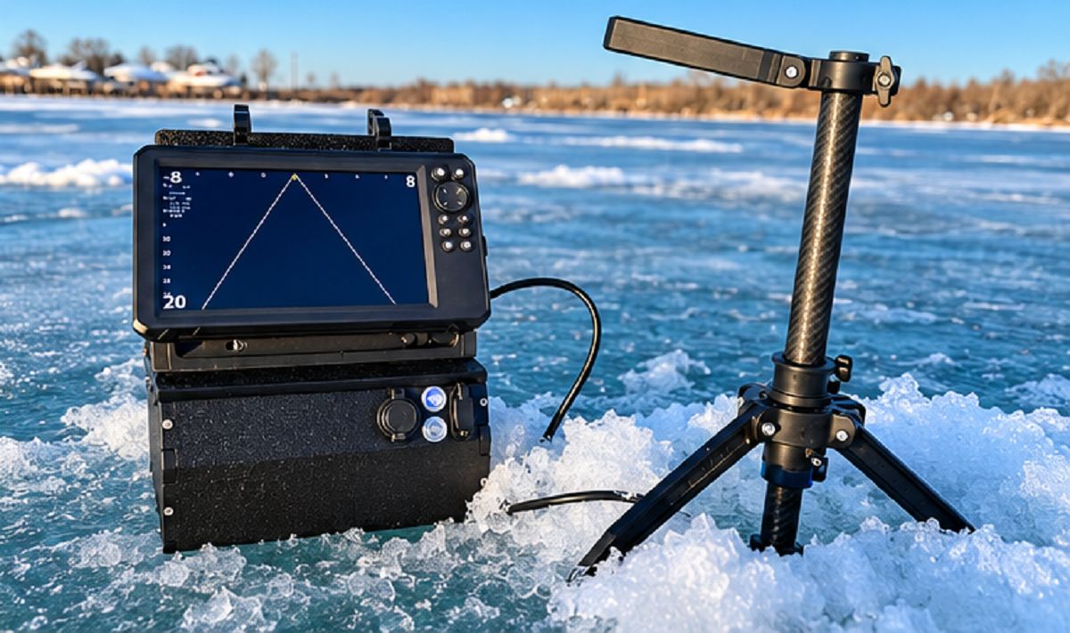
3. Compatibility and Configuration Logic
Do not rely on brand names alone. For each unit:
Locate the official installation manual for the exact model.
Note the power connector type, recommended fuse rating, and any stated limits on power-cable extension length and wire gauge.
Record the published current draw or power consumption (values change with brightness, sonar mode, and supply voltage).
Check grounding and shield/drain-wire instructions.
Confirm whether the unit is intended to be powered from a switched source.
Practical configuration points
Multiple graphs and live-sonar modules usually benefit from individual fused branches rather than a single shared feed. This improves isolation and simplifies troubleshooting.
The backbone must be sized for the total continuous current of all devices it supplies. Branches are sized for the devices on that leg only.
Factory power pigtails are often smaller gauge. When extending them, follow the manufacturer's extension tables and retain (or match) the specified fuse.
Most fish-finder and live-sonar electronics are 12 V devices even on boats that run 24 V or 36 V trolling motors. Feed them from a 12 V source or a properly regulated 12 V supply.
Approximate steady-state currents for planning (always verify with the specific manual):
Mid-size graph: roughly 1.5–3 A
Larger console graph: 2.5–4.5 A
Live-sonar module: commonly 1–1.5 A under normal operation
Full multi-unit system: often 8–15 A continuous
4. Wire Gauge and Voltage Drop
ABYC E-11 treats electronic equipment as a critical circuit and applies a 3 % maximum voltage-drop limit. On a nominal 12 V system that equals 0.36 V, calculated on the full round-trip length (positive conductor + negative return). Always consult the current edition of the standard for exact wording, ampacity tables, and any applicable exceptions.
A common calculation method used with this approach is:
CM required = (10.75 × I × L) / E
where
I = current in amperes
L = round-trip length in feet
E = allowable drop in volts (0.36 for 12 V at 3 %)
The conductor must also satisfy ampacity requirements for its insulation temperature rating and installation conditions. On longer runs, voltage drop usually governs the final size. Voltage-drop compliance alone does not guarantee that ampacity, overcurrent protection, or installation conditions are correct.
Minimum AWG to stay at or under 0.36 V (copper, 12 V system, round-trip length)
Values are derived from the formula above and rounded to the next common size that satisfies the limit. Also verify ampacity, temperature, and connection quality. Many installers select one size larger for real-world margin and future expansion.
|
Total Amps |
30 ft RT |
40 ft RT |
50 ft RT |
52 ft RT |
|
5 A |
12 AWG |
12 AWG |
10 AWG |
10 AWG |
|
10 A |
10 AWG |
8 AWG |
8 AWG |
8 AWG |
|
15 A |
8 AWG |
6 AWG |
6 AWG |
6 AWG |
|
20 A |
6 AWG |
6 AWG |
4 AWG |
4 AWG |
|
25 A |
6 AWG |
4 AWG |
4 AWG |
4 AWG |
|
30 A |
4 AWG |
4 AWG |
2 AWG |
2 AWG |
Backbone versus branch
The backbone (battery to the switch panel or distribution point) carries the total current and must be sized for that total and the longest path. Individual branches carry only the current of the devices on that leg. The voltage drop on the backbone plus the drop on each branch must remain inside the overall 3 % budget.
For a typical 8–15 A multi-unit load and 40–52 ft round-trip, an 8 AWG or 6 AWG backbone is commonly used. Branches are often 10 AWG or 12 AWG once near the units.
Overcurrent protection
The fuse or breaker protects the wire. Size it according to the ampacity of the conductor it protects. ABYC E-11 requires an overcurrent device within 7 inches of the point where the ungrounded conductor connects to the source of power, measured along the conductor. Limited exceptions exist when the conductor is contained throughout its length in a sheath or enclosure; those longer distances are conditional and must be verified against the current edition of the standard.
A practical arrangement is a main fuse or breaker near the battery plus individual fuses at the switch panel for each branch. Lithium batteries can deliver higher fault current; confirm that the chosen protection devices have an adequate interrupt rating for the battery chemistry in use.
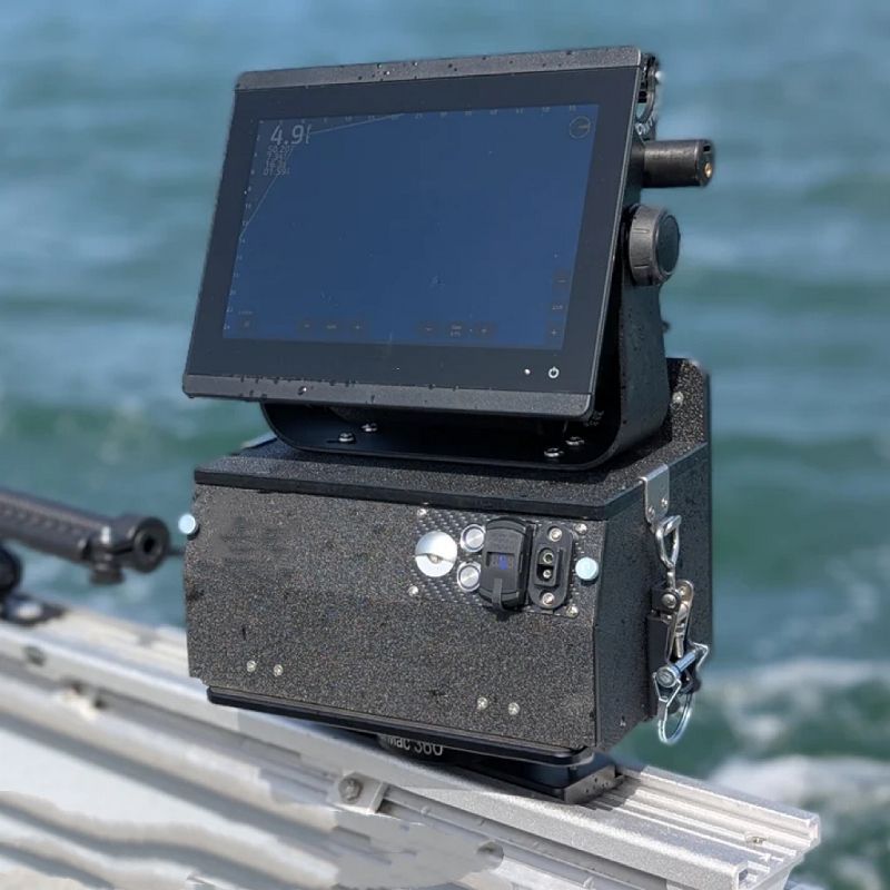
5. Noise Control Principles
After voltage delivery is adequate, reduce the paths that allow electrical noise into the sonar.
Keep electronics power cables and transducer cables separated from high-current trolling-motor wiring wherever the boat layout permits. When a crossing is unavoidable, cross near 90 degrees. Avoid tight coils of excess cable; arranging excess length in a figure-8 pattern is a common practice that can reduce the antenna effect compared with a tight coil.
Shared ground paths between the trolling motor and the electronics are a frequent contributor to interference. A dedicated electronics battery or a clean common-ground arrangement can reduce that path. Follow the unit manufacturer's instructions for any shield or drain wire. Ferrite beads or chokes near the connectors on transducer and network cables are recommended in several manufacturers' guidance as additional filtering. Exact solutions depend on the interference path and the specific equipment.
6. Configuration Guidance by Number of Devices
Single graph
One dedicated run of appropriate gauge, an inline fuse near the source, and clean routing is usually sufficient.
Two to four units (console + bow)
A switch-panel harness with an adequately sized backbone and individual fused, switched legs becomes practical. Confirm circuit count and measured lengths.
Multi-unit live-sonar boats
Dedicated legs for the modules, a backbone sized for total load and longest path, and deliberate separation from trolling-motor cables generally produce the most stable results.
7. Specification Checklist for Ordering
When requesting a stock or custom fishing sonar switch panel wiring harness, provide:
- Boat type and approximate length
- Battery location and type
- Number and location of graphs and live-sonar modules
- Measured one-way path lengths (console and bow)
- Preferred backbone and branch gauges
- Number of switched and fused circuits required
- Connector preference or requirements
Any special routing constraints (rigging tube diameter, side-panel path, etc.)
This information is the input a supplier needs for design confirmation. It is not a final design approval; the supplier should still verify lengths, protection, and terminations against the actual installation conditions.
Fishing Sonar Switch Panel Wiring Harness
8. Standard Harness versus Custom Harness
A standard harness works well when the boat layout, circuit count, and lengths fall inside the product's published range. Choose a custom Marine Wire Harness when path lengths differ significantly from stock, when extra circuits or heavier backbone capacity are required, or when specific connectors and labeling are needed for a particular electronics package.
9. Installation Verification and Maintenance
After installation, repeat the loaded voltage measurement at each unit. Confirm that every positive conductor is protected close to its source and that cables are supported against chafe. Label every circuit at the panel.
Once a year, or after any flooding or hard grounding, inspect terminations for corrosion, re-torque battery and bus connections, and re-check voltage under load. Most long-term problems appear at the connections rather than in the wire itself.
Frequently Asked Questions