


A marine switch panel may contain only six rocker switches, yet the wiring behind it can involve several different current ratings, connector types, circuit protection devices, and grounding arrangements. If these details are missing from the purchasing specification, suppliers may quote different materials for what appears to be the same assembly.
For marine electronics brands, boat builders, and OEM purchasing engineers, a poorly defined switch panel wiring harness can create problems long before installation. Incorrect pin assignments, undersized conductors, inadequate sealing, and unclear branch dimensions can all lead to sample revisions or production delays.
A reliable Marine Wire Harness starts with a clear electrical design and a manufacturing drawing that reflects the actual installation. Buyers need to identify not only which switches connect to which loads, but also how power is distributed, where overcurrent protection is installed, and how the cables will be routed behind the panel.
This article covers the specifications required to obtain an accurate quotation, evaluate a wiring harness manufacturer, and approve a production-ready assembly.
What Is a Switch Panel Wiring Harness?
A switch panel wiring harness is a preassembled electrical wiring system connecting a switch panel to its power source, protective devices, and controlled equipment.
In a 12V or 24V marine electrical system, the assembly may include a main power feeder, switched output branches, negative return conductors, illumination connections, crimped terminals, and protective sleeving.
A six-position rocker switch panel, for example, might control navigation lights, deck lighting, a bilge pump, a fish finder, an accessory outlet, and an auxiliary device. Each circuit can have different electrical and mechanical requirements.
The construction depends on the panel design. Some marine rocker switches use individual quick-disconnect terminals, while others connect through multi-pin housings or electronic control boards.
A Marine Wire Harness must match these interfaces without requiring installers to improvise wiring changes during final assembly.
Unlike a general-purpose industrial harness, a marine assembly must also account for moisture, salt exposure, vibration, confined routing spaces, and the electrical characteristics of onboard DC systems.
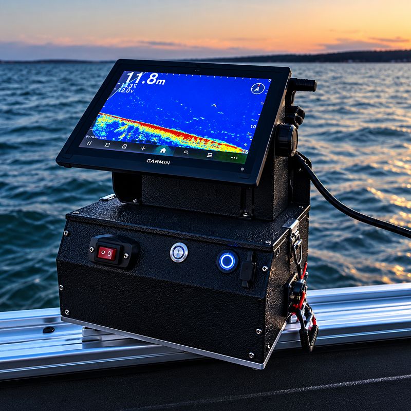
Key Specifications to Define Before Requesting a Quote
1. Wire Gauge, Current Rating, and Voltage Drop
Wire gauge selection must satisfy both conductor ampacity and acceptable voltage drop.
Ampacity determines whether a conductor can carry the required current under its installation conditions. Voltage drop determines how much supply voltage is lost as current flows through the circuit.
A wire may have sufficient ampacity but still be too small for a long 12V circuit.
ABYC E-11, AC and DC Electrical Systems on Boats, distinguishes between circuits requiring a maximum 3% voltage drop and those permitted up to 10%. Panelboard main feeders, electronic equipment, and navigation lights fall within the more restrictive category.
The American Boat & Yacht Council
Reference Wire Resistance Values
|
Wire gauge |
Approx. area |
Copper resistance at 20°C |
|
10 AWG |
5.26 mm² |
3.28 mΩ/m |
|
12 AWG |
3.31 mm² |
5.21 mΩ/m |
|
14 AWG |
2.08 mm² |
8.29 mΩ/m |
|
16 AWG |
1.31 mm² |
13.17 mΩ/m |
|
18 AWG |
0.823 mm² |
20.95 mΩ/m |
These are approximate engineering reference values for copper conductors. ASTM B258-18(2026) specifies nominal AWG dimensions and calculation rules; actual resistance must be checked against the selected wire construction and manufacturer data.
ASTM Store
Example: A 12V Fish Finder Circuit
Consider a 5A fish finder connected to a power distribution point four meters away.
Assuming equal-length positive and negative conductors, the total conductor length is eight meters.
The simplified calculation is:
Voltage drop (V) = Current (A) × Total conductor length (m) × Resistance (Ω/m)
Using 16 AWG copper:
Voltage drop = 5 × 8 × 0.01317 = 0.527V
Percentage voltage drop = 0.527 ÷ 12 × 100 = 4.39%
Using 14 AWG:
Voltage drop = 5 × 8 × 0.00829 = 0.332V
Percentage voltage drop = 0.332 ÷ 12 × 100 = 2.76%
Under these simplified conditions, 14 AWG meets the 3% voltage-drop target, while 16 AWG does not.
However, these calculations exclude connector resistance, fuse holders, switch contacts, and conductor temperature changes. The final selection must also satisfy ampacity and installation requirements.
For a custom Wiring Harness, buyers should provide the maximum current, operating voltage, one-way cable length, and voltage-drop requirement for every circuit.
2. Harness Length, Branch Dimensions, and Tolerances
Overall cable length alone is insufficient for a multi-branch switch panel assembly.
The drawing should identify where each branch begins, where it terminates, and how the dimensions are measured.
Consider this illustrative branch schedule:
|
Harness section |
Nominal finished length |
Example drawing tolerance |
|
Main power feed |
800 mm |
±10 mm |
|
Switch branch A |
150 mm |
±5 mm |
|
Switch branch B |
220 mm |
±5 mm |
|
Accessory output |
500 mm |
±10 mm |
|
Negative return |
650 mm |
±10 mm |
These tolerances are examples for preparing a drawing, not universal manufacturing capabilities or published MingChing tolerances.
The buyer and manufacturer should agree on measurement reference points, such as connector mating faces, terminal centers, or branch breakout locations.
A 500 mm cut wire is not necessarily equivalent to a 500 mm finished branch after stripping, crimping, and connector assembly.
For a tightly packed marine console, a short branch may prevent the connector from reaching the switch, while excessive length can create unnecessary cable loops behind the panel.
3. Wire Color Coding and Circuit Identification
Wire colors help installers identify power, negative return, and individual switched circuits.
For marine DC installations, color assignments should follow the applicable wiring standard and vessel design.
Common conventions include red for DC positive and yellow or black for DC negative, depending on the system. Yellow is often preferred for DC negative in vessels with AC systems because it helps distinguish DC negative conductors from AC black conductors.
Colors should never be the only means of identifying a circuit.
Each wire should have a documented function, connector destination, and pin assignment. For larger harnesses, printed identification labels can simplify installation and troubleshooting.
When a customer specifies a proprietary color system, the drawing and wiring schedule must use that convention consistently.
4. Connector Selection and Pinout Verification
Marine switch panels commonly use quick-disconnect terminals, ring terminals, and multi-pin connector systems.
The correct interface depends on the switch manufacturer, terminal dimensions, operating current, and installation environment.
For example, a rocker switch may use a nominal 6.3 mm blade terminal, but the mating terminal must still match the switch's specified dimensions and current rating.
For detachable panels, sealed multi-pin connectors may reduce installation work and make future servicing easier.
A complete connector specification should identify the housing part number, terminal part number, cavity numbering, wire seals, and mating connector.
Connector Pinout Example
|
Pin |
Electrical function |
Example color |
|
1 |
+12V input |
Red |
|
2 |
DC negative |
Yellow |
|
3 |
Switched output |
Blue |
|
4 |
Panel illumination |
White |
This table illustrates a possible configuration, not a standardized connector pinout.
The drawing must specify whether the connector is viewed from the mating face or wire-entry side. Reversing these views can produce an electrically incorrect assembly even when the terminal positions appear consistent.
For an OEM project, the connector manufacturer's datasheet should be included in the technical package.
5. Fuse, Circuit Breaker, and Power Distribution Requirements
A marine switch controls an electrical load, but it does not automatically provide overcurrent protection.
Fuses and circuit breakers protect conductors against excessive current when correctly selected and installed.
A fuse generally requires replacement after operation, while a circuit breaker can normally be reset after the fault has been identified and corrected.
Neither is universally preferable. Selection depends on current rating, trip characteristics, interrupting capacity, installation space, and service requirements.
Where Should Overcurrent Protection Be Located?
Protection location is particularly important for the main power feed supplying a switch panel.
Marine industry guidance based on ABYC E-11 commonly identifies a 7-inch (175 mm) protection distance from the relevant power-source connection, with 40-inch (1.02 m) and 72-inch (1.83 m) exceptions under specified enclosure and connection conditions.
These distances are not interchangeable installation options. Their applicability depends on the conductor routing, power source, additional protection, and the specific requirements of the applicable E-11 edition. Engine starter circuits may have separate exceptions.
Blue Sea Systems+1
A fuse located only at the switch panel may leave the upstream feeder insufficiently protected if the power source is several meters away.
The RFQ should therefore identify the main feeder protection, branch protection devices, fuse or breaker ratings, and their locations.
6. Negative Busbars, Grounding, and Electrical Noise
Marine DC systems frequently use negative busbars to organize return connections.
The busbar must have an appropriate current rating, and each connection must use a compatible terminal and fastening arrangement.
The wiring drawing should show both positive and negative paths. Omitting the negative return makes it difficult to verify conductor sizing and voltage drop.
DC negative return, protective grounding, and bonding serve different functions. Their connections must follow the vessel's electrical design and applicable marine requirements.
For fish finders and sonar equipment, grounding and cable routing deserve additional attention because sensitive electronics may be affected by voltage instability or electrical interference.
Power cables should be routed according to the equipment manufacturer's instructions, with appropriate separation from noise-producing equipment where required.
A switch panel wiring harness may supply the sonar equipment, but its power connections should not be confused with dedicated transducer or data cables.
7. Marine Wire Protection, Terminal Plating, and IP67
Tinned copper stranded conductors are widely used in marine wiring because tinning helps reduce corrosion at exposed copper surfaces.
Terminal material, plating, sealing, and mechanical support are equally important.
Tin-plated terminals are common in electrical connectors, while other contact finishes may be required for specialized interfaces. Buyers should specify the connector manufacturer's approved terminal system rather than choosing plating independently.
Protective options include braided sleeving, corrugated conduit, adhesive-lined heat shrink, cable seals, and strain-relief components.
Does Every Marine Harness Need IP67?
No. The required ingress protection depends on the installation location.
|
Installation environment |
Specification approach |
|
Protected interior console |
Assess moisture, condensation, and mechanical exposure |
|
Splash-prone cockpit |
Consider sealed connectors and splash protection |
|
Exposed deck equipment |
Evaluate water exposure, UV, corrosion, and sealing |
|
Portable sonar enclosure |
Evaluate repeated mating, cable movement, and moisture exposure |
|
Temporary immersion risk |
Specify and verify the appropriate ingress-protection requirement |
IEC 60529 defines the IP classification system. Its consolidated Edition 2.2 incorporates the 1989 publication and the 1999 and 2013 amendments.
IEC
IP67 addresses dust protection and temporary immersion under specified test conditions. It does not automatically establish resistance to prolonged saltwater exposure, pressure washing, or corrosion.
An IP67-rated connector also does not make the complete Wiring Harness IP67-rated. The mated connector, wire seals, cable entries, and relevant assembly boundaries must be evaluated.
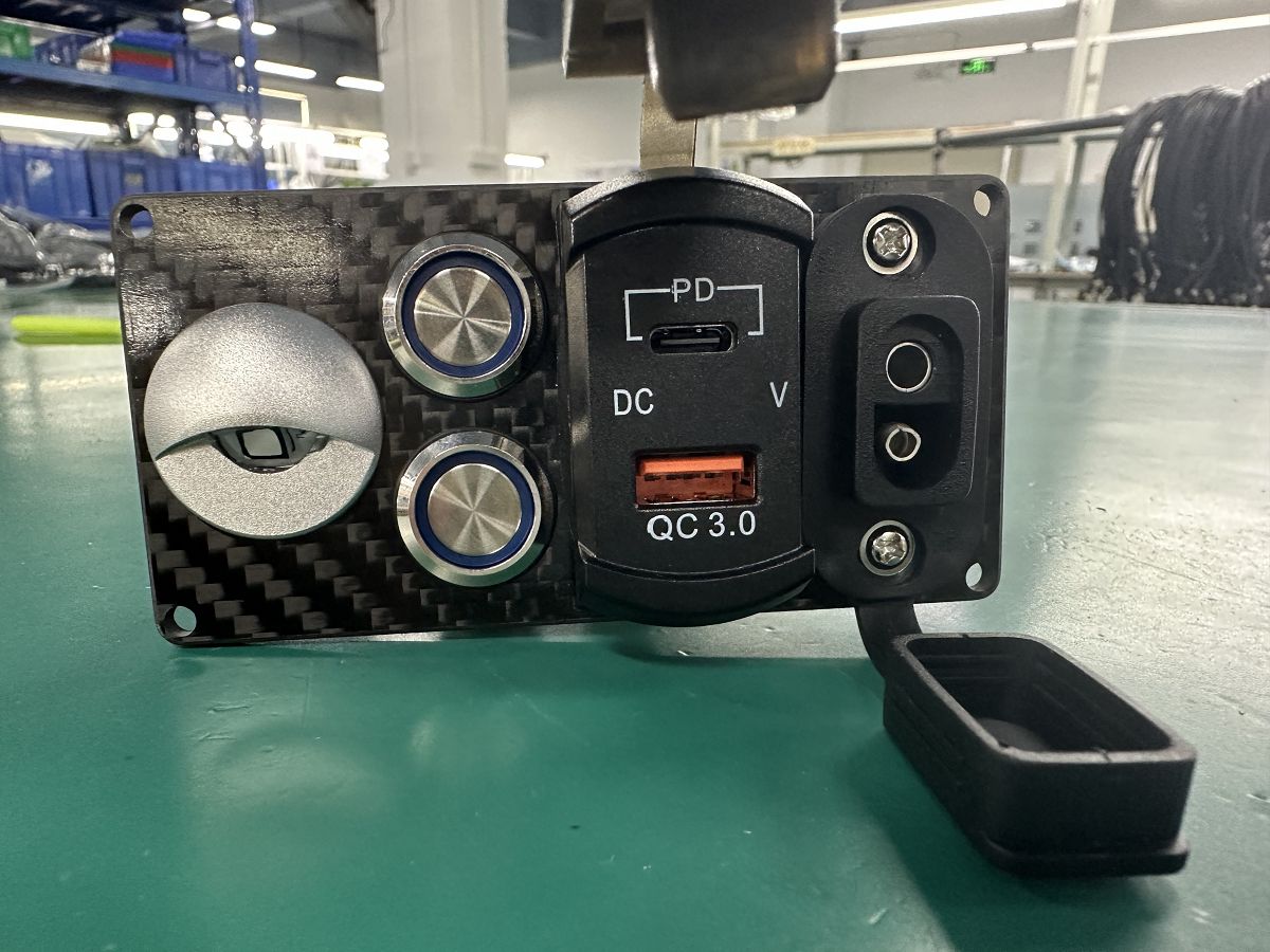
Common Mistakes in Custom Marine Harness Orders
Undersizing the Main Power Feed
A six-switch panel may supply loads with substantially different current requirements. Selecting the main conductor according to a single switch rating ignores the combined load.
The engineering drawing should identify the intended simultaneous current and the upstream protection arrangement.
Confusing Rocker Switch Terminal Functions
Illuminated rocker switches may have separate terminals for supply, output, negative return, and indicator illumination.
Similar-looking switches can have different terminal assignments. The exact switch datasheet should be used rather than assuming a standard layout.
Leaving Connector Orientation Undefined
A connector diagram without a viewing direction can result in reversed pin assignments.
The approved drawing should include cavity numbering, viewing direction, and a pin-to-pin connection table.
Ignoring Installation Clearance
A harness may pass electrical inspection but still be difficult to install because its branches are too short, its connectors are too large, or its wires bend sharply near terminals.
Installation photographs and dimensional references help identify these issues before sample approval.
Treating Waterproofing as a Single Component
A sealed connector does not compensate for damaged insulation, missing cavity plugs, incorrectly sized wire seals, or unsupported cables.
Environmental protection should be evaluated across the complete connection system.
Engineering Review: Two Marine Switch Panel Risk Scenarios
The two cases below are technical design-review examples, not claims about completed customer orders.
Case 1: Undefined Power Distribution in a Six-Circuit Panel
A drawing identifies six switched outputs but does not specify the combined feeder current or the location of upstream protection.
The missing information affects conductor sizing, fuse selection, and the safety of the power distribution arrangement.
Before manufacturing, the buyer should provide a circuit load schedule showing maximum current, simultaneous operation, feeder length, and protection requirements.
The manufacturer can then build the assembly to the approved design rather than making assumptions about the vessel's electrical system.
Case 2: Reversed Pinout on a Detachable Sonar Panel
A four-pin connector drawing identifies the electrical functions but omits the viewing direction.
If the assembler interprets the pinout from the wire-entry side while the equipment designer intended the mating-face view, the resulting connections may be reversed.
The solution is to use the connector manufacturer's cavity diagram, define the orientation explicitly, and verify every circuit during sample testing.
For production, a pin-to-pin test specification provides an objective acceptance criterion.
What Documents Should You Send Your Manufacturer?
A complete request-for-quotation package reduces technical uncertainty and makes supplier quotations easier to compare.
Marine Switch Panel Wiring Harness RFQ Checklist
|
Category |
Information to provide |
Acceptance check |
|
Electrical system |
12V/24V DC, voltage range |
Matches equipment requirements |
|
Circuit loads |
Maximum current and duty cycle |
Every branch has a defined load |
|
Wire gauge |
AWG, conductor material, insulation |
Ampacity and voltage drop checked |
|
Harness dimensions |
Main length, branch lengths |
Reference points and tolerances defined |
|
Wire colors |
Color and circuit identification schedule |
Matches approved wiring diagram |
|
Connectors |
Housing, terminal, seal part numbers |
Mating compatibility verified |
|
Connector pinout |
Pin number, function, orientation |
Mating-face or wire-entry view identified |
|
Switch interface |
Rocker switch model and terminal arrangement |
Datasheet matches the harness |
|
Circuit protection |
Fuse/breaker ratings and positions |
Feeder and branch protection reviewed |
|
Negative return |
Busbar and return-path arrangement |
Grounding functions distinguished |
|
Environmental protection |
Moisture, salt, vibration, IP requirements |
Materials and tests specified |
|
Testing |
Continuity, shorts, crimp inspection |
Acceptance criteria documented |
|
Purchasing |
Sample quantity, MOQ, annual demand |
Quote and lead time confirmed |
|
Revision control |
Drawing number and revision |
Latest approved documents used |
The RFQ should include a wiring harness drawing, electrical schematic, connector datasheets, bill of materials, and installation photographs where available.
An existing physical sample is useful when replacing a legacy assembly, but it should be accompanied by confirmed electrical requirements.
How Samples and Testing Reduce Production Risk
A production sample should be evaluated electrically, mechanically, and dimensionally.
Continuity testing verifies intended connections. Short-circuit testing identifies unintended connections, while pinout verification confirms that every conductor terminates in the correct connector cavity.
Crimp pull-force testing evaluates terminal retention against the selected terminal system and applicable workmanship requirements.
Dimensional inspection checks branch lengths, connector positions, and specified tolerances.
For marine assemblies, buyers may also require environmental tests, including sealing or corrosion-related testing, depending on the application.
IPC/WHMA-A-620 is an established workmanship and acceptance standard for cable and wire harness assemblies. IPC's published revision history identifies Revision E, issued in October 2022. The contract should specify the edition and applicable acceptance class.
IPC Resources
A supplier's use of this standard should not be confused with an independent certification claim.
For production orders, the approved sample, drawing revision, and test requirements should remain aligned. This helps prevent a later batch from being manufactured to outdated connection information.
How to Evaluate a Custom Wiring Harness Manufacturer
A low unit price does not necessarily indicate the lowest project cost.
Connector substitutions, insufficient inspection, unclear revision control, and repeated sample changes can increase total procurement costs.
When comparing manufacturers, request evidence that can be reviewed rather than relying only on capability statements.
|
Evaluation area |
Evidence to request |
|
Engineering support |
Reviewed drawing with documented technical questions |
|
Manufacturing capability |
Current production equipment and workshop photographs |
|
Crimp quality |
Crimp specifications and inspection records |
|
Electrical testing |
Sample continuity and pinout test reports |
|
Materials |
Connector and wire manufacturer part numbers |
|
Revision control |
Drawing revision and production change records |
|
Quality management |
Valid certificate with issuing body and scope |
|
Production consistency |
Lot identification and traceability records |
|
Commercial capability |
Written MOQ, sample terms, tooling cost, and lead time |
Custom Wiring Harness Manufacturing at MingChing
MingChing Electronics Technology Co., Ltd. was established in Shenzhen, China, in 2009. We manufacture custom wiring harnesses and cable assemblies for industrial equipment, vehicles, marine electronics, and other OEM electrical applications.
Our manufacturing operations include cable processing, assembly, and injection-molding capabilities, with more than 500 production employees.
For marine projects, we manufacture custom power and connection harnesses, including assemblies designed to interface with switch panels, fish finders, and portable sonar equipment. Our scope covers the wiring assembly rather than the finished switch panel.
We can review customer drawings, BOMs, and existing samples. Custom orders start from 10 pieces, with typical bulk production planning of 2–4 weeks after design approval and material readiness for conventional assemblies.
Buyers can review our company and product information at MingChing Electronics. For supplier qualification, request current certificates, factory photographs, inspection records, and project-specific manufacturing documentation directly.
Frequently Asked Questions
Request a Custom Switch Panel Wiring Harness Quote
A successful switch panel wiring harness project begins with a complete understanding of the marine electrical system.
Correct conductor sizing, accurate pin assignments, suitable overcurrent protection, corrosion-resistant connections, and clear installation dimensions all contribute to a more reliable assembly.
A detailed RFQ checklist also helps purchasing teams compare quotations on the same technical basis.
Before placing a production order, confirm the drawing revision, inspect the sample, review the test requirements, and verify the manufacturer's capabilities.
For OEM marine electronics projects, MingChing can review your wiring diagram, BOM, connector information, or existing harness sample and discuss custom manufacturing requirements.