The Conductor Is Not "One Solid Wire" - It Is Made of Multiple Ultra-Fine Copper Strands
If you have ever cut open an ordinary household electrical wire, you may have seen a single solid copper core-rigid and stiff, and likely to break after being bent several times.
But the conductor used in high-quality diagnostic cable assemblies is completely different.
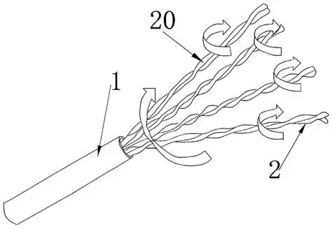
It is not "one solid wire"; instead, it consists of multiple ultra-fine copper strands twisted together-much like braiding a rope.
A thick copper wire is replaced by dozens or even hundreds of extremely fine copper strands. The diameter of each individual strand is typically less than 0.2 mm, while high-quality cables can use strands as fine as 0.05–0.10 mm. These strands are then spirally twisted together to form a multi-strand conductor.
This "braided" design solves one fundamental problem: flexibility.
When a solid copper wire is bent, the outer side is stretched while the inner side is compressed, causing stress to concentrate at the bending point-after repeated bending, the wire can eventually break.
With multiple fine copper strands twisted together, each individual strand can move slightly relative to the others during bending. External forces are distributed across the individual strands instead of being concentrated in one thick copper wire.
It is like comparing a bundle of chopsticks with a single chopstick: a single chopstick can easily snap when bent, while a bundle of chopsticks is much harder to break. The same principle applies to multi-strand fine copper conductors: the more strands there are and the finer they are, the softer and more fatigue-resistant the overall cable becomes.
Industry testing data clearly demonstrates the difference:
High-flexibility drag-chain cables use multi-strand, ultra-fine, finely stranded oxygen-free copper conductors that comply with Class 6 conductor requirements under DIN VDE 0295 or IEC 60288. In 10 million bending cycles, the breakage rate of multi-strand copper conductors is more than 90% lower than that of rigid conductors.
Rigid-conductor cables can begin to experience strand breakage after just 5 million bending cycles.
Conductors using 0.08 / 0.10 / 0.12 mm ultra-fine copper strands can withstand at least 1 million reciprocating bending cycles at a standard bending radius of 7.5 times the cable's outer diameter, with no broken strands or insulation breakdown.
Higher-specification products can achieve bending lifetimes of 6–8 million cycles, or even 20 million cycles.
The finer the copper strands, the greater the number of strands, and the shorter the stranding pitch, the softer and more bend-resistant the cable becomes. This is why a high-quality diagnostic cable assembly can be repeatedly coiled, bent, and stored without internal core breakage.
The Elastomer Jacket Provides "Self-Recovery"
The conductor provides flexibility, but flexibility alone is not enough. A cable also needs the ability to return to its original shape after bending.
This is where the elastomer jacket comes in.
PUR (polyurethane) is a thermoplastic elastomer with a unique molecular structure consisting of alternating hard segments and soft segments.
The hard segments provide strength and abrasion resistance, while the soft segments provide flexibility and elastic recovery.
When the cable is bent, the molecular chains in the soft segments rotate and stretch to absorb deformation energy. When the external force is removed, the hard segments act like springs, pulling the molecular chains back toward their original positions.
Real-world test data makes the difference even clearer:
PUR jackets can achieve an elongation at break of up to 400%, far exceeding the approximately 150% typical of conventional PVC materials.
After repeated bending, PUR can maintain a rebound rate of more than 95%.
In standard abrasion testing according to ISO 4649, PUR exhibits a much lower volume loss due to abrasion than traditional PVC and rubber materials.
Simply put, a PUR jacket is like a high-quality rubber band: stretch it and it elongates; release it and it springs back. This "self-recovery" capability ensures that the cable does not develop permanent deformation during repeated bending, while the outer jacket does not wrinkle, bulge, or crack.
If you are interested in more technical details about PUR materials, see our previous article, "Why Is a PUR Jacket the 'Protective Shield' of Automotive Cable Assemblies?"
How the "SR Strain-Relief Boot" Transfers Pulling Force to the Housing Instead of the Internal Solder Joints
A flexible conductor and an elastic jacket are important-but the parts of a cable that are most vulnerable to failure are actually not in the middle, but at both ends.
The connection between the OBD connector and the cable is the transition point between a rigid component (the connector) and a flexible component (the cable).
Every time the connector is plugged in or unplugged, or every time the cable is pulled, forces become concentrated at this transition point. Without proper protection, the internal solder joints are repeatedly subjected to mechanical stress, eventually becoming loose and breaking.
This is exactly the problem that the SR (Strain Relief) boot is designed to solve.
The working principle of the SR strain-relief boot is quite clever: it does not make the cable "bear" the pulling force; instead, it makes the pulling force "bypass" the internal solder joints.
When an external force pulls on the cable, the SR boot-an elastic structure integrally molded at the rear of the connector-comes into action.
Step 1: Grip
The SR boot firmly grips the outer jacket of the cable, leaving virtually no room for relative movement.
The pulling force is therefore applied to the boot rather than being directly transferred to the internal solder joints.
Step 2: Transfer
The boot transfers the pulling force to the connector housing-either the plastic housing or the metal shielding shell-instead of transferring it to the delicate internal solder joints.
The Result
When you pull the cable forcefully, the strain-relief boot intercepts the force, so the internal solder joints experience virtually no tensile load.
How Effective Is This Design?
According to the stress-relief testing requirements of the international standard IEC 60884-1, a plug must withstand a 60 N pulling force (approximately 6 kg) applied 100 times at a frequency of once per second.
A cable equipped with a qualified SR boot can easily pass this test, with the internal solder joints remaining intact and electrical performance unaffected.
What happens without an SR boot?
After only a few pulling cycles, the internal solder joints may begin to loosen, resulting in intermittent signals, interrupted ECU programming, and ultimately a completely unusable cable.
Conclusion
| Component | Problem Solved | How It Works | Key Data |
|---|---|---|---|
| Multi-strand twisted conductor | Core breakage after repeated bending | Ultra-fine copper strands distribute mechanical stress | 10 million bending cycles; 90%+ lower strand breakage rate than rigid conductors |
| PUR elastomer jacket | Permanent deformation and poor recovery after bending | Hard-segment + soft-segment molecular structure provides self-recovery | 400% elongation at break; 95%+ rebound rate |
| SR strain-relief boot | Solder-joint breakage caused by plugging, unplugging, and pulling | Transfers pulling force to the housing and protects the solder joints | Passes 60 N × 100 pull-force test |
"High flexibility" is not achieved by a single material or a single component-it is the result of the coordinated interaction of conductor stranding technology, jacket material science, and connector structural design.
Multi-strand ultra-fine copper conductors prevent core breakage during millions of bending cycles; PUR elastomer jackets allow the cable to return to its original shape after every bend; and SR strain-relief boots protect the internal solder joints from the mechanical stress caused by repeated plugging, unplugging, and pulling.
It is the combination of these three layers of protection that creates a truly "high-flexibility, pull-resistant" diagnostic cable assembly.
Two cables may look almost identical on the outside, yet internally, they may differ by three generations of engineering technology.