The Internal Structure of a High-Quality OBD to RJ45 Diagnostic Cable Harness
From the outside, a qualified OBD-to-RJ45 diagnostic cable harness looks like nothing more than a cable with two different connectors on both ends.
However, when you look inside, the entire cable assembly consists of three core components:
① OBD Connector - The Vehicle-Side Interface
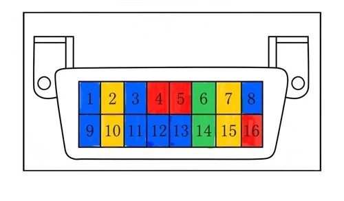
This is a 16-pin trapezoidal male connector that complies with the SAE J1962 standard.
Its purpose is to connect directly to the vehicle's OBD diagnostic port, typically located underneath the steering wheel.
② Cable Assembly - The "Blood Vessel" for Data Transmission
This is the section connecting the OBD connector and the RJ45 connector.
It is not an ordinary electrical wire, but a Shielded Twisted Pair (STP) cable.
Its role is to ensure stable high-speed data transmission while protecting signals from electromagnetic interference in the vehicle environment.
③ RJ45 Connector - The Computer-Side Interface
A standard 8-pin Ethernet connector designed to plug into a laptop or PC network port.
It provides the communication link between the vehicle diagnostic system and the computer.
Although these three components may sound simple, the real quality difference is hidden in the details.
Internal Breakdown: The Manufacturing Process Behind Each Component
🔌 Inside the OBD Connector: More Than Just a Plastic Housing
When the plastic shell of an OBD connector is opened, a precision internal structure can be found.
① Gold-Plated Terminals
The 16 pins inside the OBD connector are contact terminals stamped from copper material.
High-quality cable harnesses apply gold plating treatment to the terminal surfaces.
Gold plating is not for appearance - it is for electrical performance.
Gold has extremely low contact resistance and excellent oxidation resistance.
In automotive diagnostic applications, signal transmission stability directly determines whether the diagnostic process succeeds.
Low-quality cables often use nickel-plated or bare copper terminals. After long-term use, oxidation may occur on the contact surface, increasing contact resistance and potentially causing:
Data packet loss
Communication interruptions
ECU programming failures
② PCB Adapter Board (Printed Circuit Board Adapter)
The 16 OBD pins are not directly soldered to the cable wires.
Instead, there is a PCB adapter board inside the connector.
The pins are first soldered onto the PCB, and the cable wires are then connected to the other side of the PCB.
The PCB serves two main purposes:
• Precise Pin Positioning
It ensures that all 16 pins are accurately aligned according to the hole positions defined by the SAE J1962 standard.
• Provides a Reliable Soldering Platform
It organizes and connects the small signal wires to their corresponding pins in a structured and reliable way.
③ Injection-Molded Inner Structure (Injection Molding Overmold)
This is one of the most critical manufacturing processes in OBD connector production.
The terminals are precisely positioned inside a mold. The injection molding machine then closes the mold and injects molten plastic material. After cooling and solidification, the terminals become firmly integrated with the plastic housing.
Injection molding is not simply "putting a cover over the connector."
It creates a unified structure where the plastic body and metal terminals are integrally molded together, leaving no room for movement.
The advantages include:
• Vibration Resistance
Vehicle vibration and road shocks will not easily loosen internal solder joints.
• Dust and Water Protection
The one-piece molded structure reduces gaps and improves environmental protection.
• Compact Design
No additional space is required for screws or mechanical clips, allowing a smaller and more efficient connector structure.
④ Strain Relief
At the rear of the OBD connector, where the cable exits, you will find an integrally molded PVC strain relief boot.
This small and often overlooked component is actually extremely important.
During use, diagnostic cables are repeatedly:Plugged and unplugged,Bent,Pulled.
Without strain relief, all mechanical stress would directly transfer to the internal solder joints.
Over time, this can cause:
- Solder joint cracking
- Wire breakage
- Intermittent communication failures
The purpose of the strain relief is to distribute and absorb external mechanical stress, protecting the internal solder connections from excessive force.
🔌 Inside the Cable: More Than Just "A Few Copper Wires"
Strip away the outer jacket of the cable, and you will find several critical components inside:
① Aluminum Foil Shielding
High-quality diagnostic cable harnesses feature a layer of aluminum foil shielding wrapped around the twisted pairs. Some cable assemblies also include a braided shield, providing dual-layer shielding.
The inside of a vehicle is an environment with extremely high levels of electromagnetic interference (EMI). Alternators, ignition coils, electric motors, relays, and other electrical components continuously generate electromagnetic noise. Without proper shielding, this interference can couple into the signal lines, potentially causing data transmission errors and ECU flashing failures.
The shielding layer works like a Faraday cage, blocking external electromagnetic fields from reaching the signal conductors.
② Twisted Pair
Inside the shielding layer, the signal conductors are twisted together in pairs. Tx+ and Tx− are twisted together, while Rx+ and Rx− are twisted together.
The principle behind twisted-pair wiring is to tightly twist the two signal conductors so that they are exposed to nearly identical electromagnetic conditions. When interference occurs, nearly identical noise is induced on both conductors.
The receiver detects only the voltage difference between the two conductors - the differential signal. Because the same noise appears on both wires, it is largely canceled out, allowing the useful signal to pass through with minimal interference.
③ Pure Copper Conductors
High-quality cable harnesses use 24AWG or 28AWG pure copper conductors.
Lower-quality cables may use copper-clad aluminum (CCA) or copper-clad steel, which have higher electrical resistance and greater signal attenuation.
For high-speed Ethernet diagnostics at 100 Mbps or even 1 Gbps, conductor quality directly affects how far and how reliably the signal can be transmitted.
🔌 Inside the RJ45 Connector: More Than Just a "Modular Plug"
The RJ45 end also contains several important design details:
① Gold-Plated Contacts
Just like the terminals on the OBD side, the metal contacts inside the RJ45 connector should also feature gold plating to provide low contact resistance and long-term oxidation resistance.
② Shielded Metal Housing
High-quality RJ45 connectors use a metal shielded housing connected to the cable's shielding layer.
This creates a continuous shielding path from the vehicle to the computer, helping protect the high-speed Ethernet signal from external electromagnetic interference.
③ Overmolding
Like the OBD connector, the RJ45 connector also features an injection-molded strain relief at the cable exit.
It protects the internal connections and solder joints from damage caused by repeated pulling, bending, and mechanical stress.
The Function of Each Component at a Glance
| Component | Location | Function |
|---|---|---|
| Gold-Plated Terminals | Inside OBD connector | Low contact resistance, oxidation resistance, and stable signal transmission |
| PCB Adapter Board | Inside OBD connector | Precisely positions the pins and connects all 16 pins to the corresponding signal wires |
| Injection-Molded Inner Structure | OBD connector housing | Integrated construction for vibration, dust, and water resistance, minimizing the risk of internal movement |
| Strain Relief | Cable exits of both connectors | Absorbs mechanical pulling forces and protects internal solder joints from being damaged |
| Aluminum Foil Shielding | Inside the cable | Blocks external electromagnetic interference (EMI) and protects data integrity |
| Twisted Pair | Inside the cable | Enables differential signal transmission and helps cancel common-mode noise |
| Pure Copper Conductors | Inside the cable | Low resistance and low signal attenuation for high-speed data transmission |
| Gold-Plated Contacts | Inside RJ45 connector | Low contact resistance and reliable Ethernet connection |
| Shielded Metal Housing | Exterior of RJ45 connector | Extends the cable shielding and creates continuous electromagnetic protection |
In One Sentence
A properly engineered diagnostic cable harness has a purpose behind every layer, from the outside all the way to the core.
The injection-molding process of the OBD connector provides a secure, durable connection designed to withstand years of repeated plugging and unplugging. The cable's shielded twisted-pair construction protects every bit of data from the electromagnetic noise surrounding the engine compartment. The strain reliefs at both ends absorb pulling and bending forces to prevent cable failure, while gold-plated contacts ensure stable and reliable electrical connections every time.
Two cables may look almost identical on the outside, yet the difference inside can determine whether one delivers years of reliable service while another fails after only a handful of uses.
When choosing a diagnostic cable harness, don't look at price alone - every layer of internal construction matters, and every manufacturing detail can determine whether your ECU programming process completes successfully or is interrupted halfway through.