


Distribution cabinet wiring usually fails because one connection develops high contact resistance, or because a conductor cannot shed its heat. The common triggers are an under-torqued screw terminal, a poor crimp, an undersized or un-derated wire, a mismatched terminal, damaged strands and poor routing. A controlled harness process prevents the manufacturing-side causes. Installation torque, electrical design and the operating environment must still be handled separately.
A cabinet can run normally for months before one connection starts to overheat. The first sign is often an intermittent shutdown that leaves no trace in the PLC log. Later, someone finds a discolored terminal, or insulation that has gone brittle next to a lug. The breaker was fine and the load was normal, but one joint had been getting hotter with every load cycle.
This article covers low-voltage power distribution and control cabinets (up to 1,000 V AC) built from copper conductors, lugs, ferrules and screw or spring terminals. Medium-voltage switchgear and aluminum busbar systems have their own failure modes and are not covered. The same causes also affect the sensor cable assembly and servo motor cable assembly runs that connect a cabinet to the machine; a dedicated section below explains where their priorities differ. It is written for cabinet builders, equipment OEMs, and the maintenance and purchasing engineers who inspect their wiring.
They are ordered by logic, from the connection outward to the layout, not by statistical frequency. We have not seen a reliable public failure-rate breakdown, so we do not rank them by share of failures. Causes 1 to 6 can lead to overheating. Cause 7 does not, but it is included because it is a common reason a new cabinet fails at commissioning.
Why Do Cabinet Connections Overheat? Resistance, Heat and Thermal Cycling
Heat generated at a joint follows P = I²R, where P is power lost as heat, I is current and R is the resistance of the joint. Because heating rises with the square of the current, a small increase in resistance matters more on a heavily loaded feeder than on a lightly loaded control wire.
Failure is rarely a single event. A joint with slightly high resistance runs warmer. The metals expand and contract on every load cycle, and vibration adds movement. Contact pressure drops, the surface oxidizes, resistance climbs and the joint runs hotter again. Several causes below start this loop. Thermal cycling and vibration are what make them worse; they are not a separate cause.
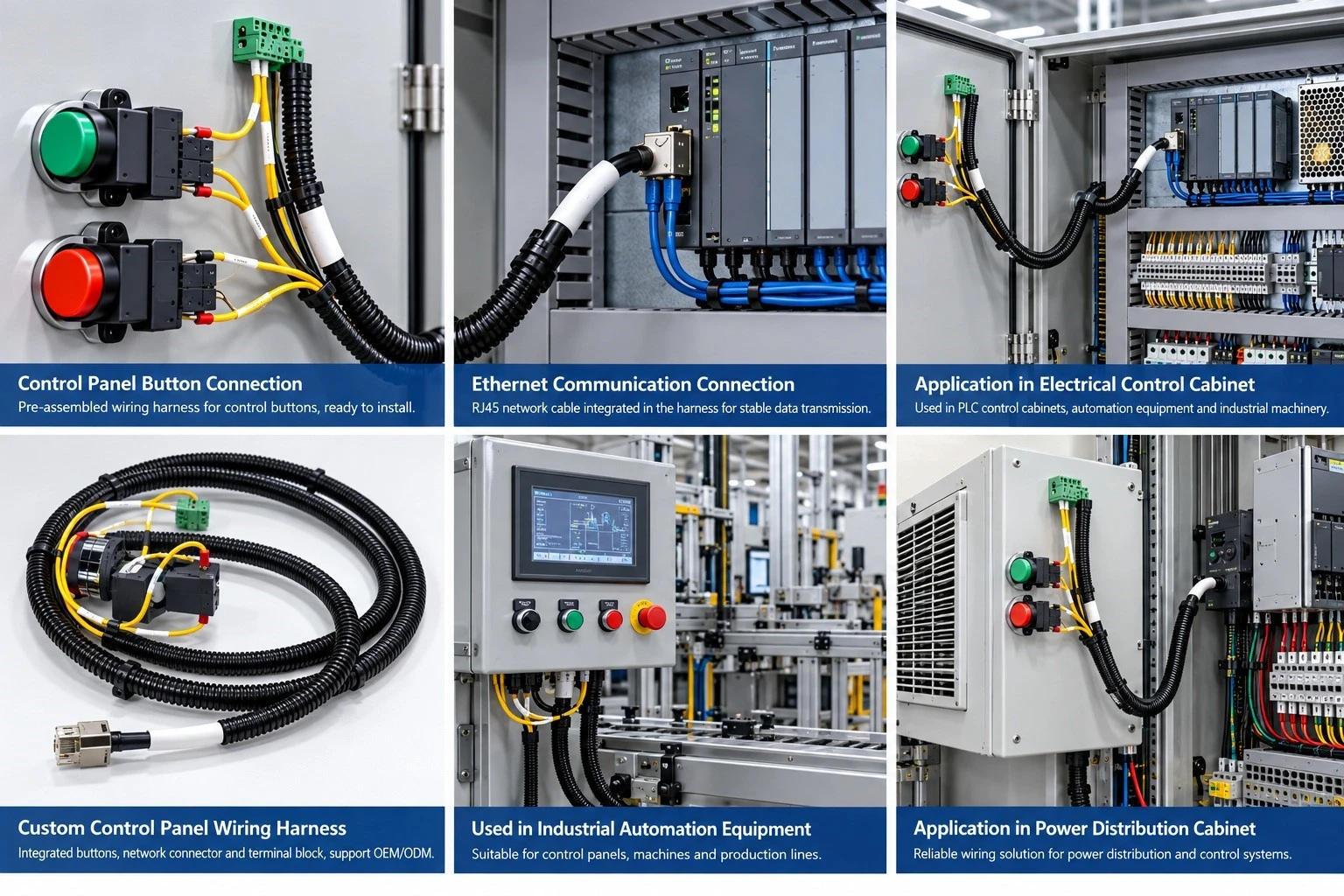
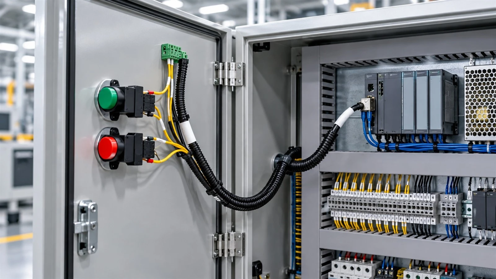
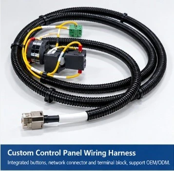
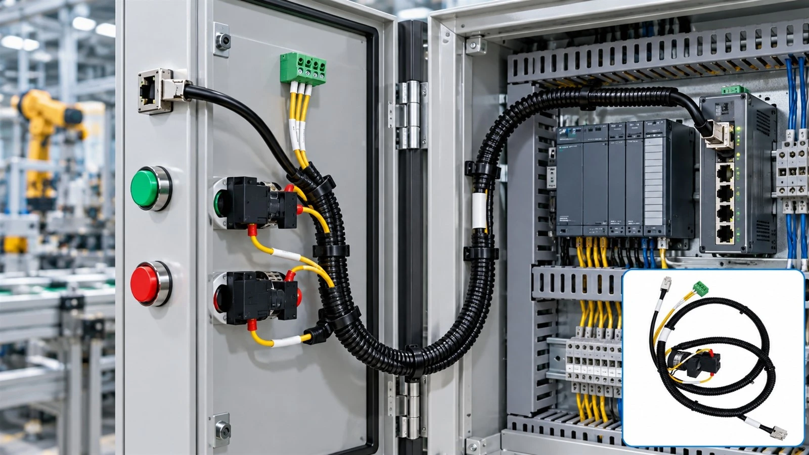
In this article, a terminal is the metal part that connects a conductor to a device. A lug is a ring or fork terminal, usually bolted. A ferrule is a sleeve on a stranded wire end, used in clamp-type terminals. A wire harness is a prefabricated, tested assembly of cut, stripped, terminated and marked conductors.
Who Controls Which Cause: Harness Manufacturer, Designer or Installer?
Many cabinet failures are blamed on the wrong party. This table separates who mainly controls each cause. It reflects our production experience; it is a judgment, not a statistic.
|
Cause |
Mainly controlled by |
What a harness supplier can contribute |
|
1. Loose screw terminals |
Cabinet assembly and installation |
Terminals matched to the device; torque and witness-mark notes on the drawing |
|
2. Poor crimping |
Harness manufacturing |
Tooling, setup checks, pull-force and crimp inspection |
|
3. Undersized wire / no derating |
Electrical design |
Check the wire list for buildability; record the customer's derating assumptions |
|
4. Terminal mismatch |
Harness manufacturing and BOM control |
Revision-controlled BOM; first-article inspection |
|
5. Stripping damage |
Harness manufacturing |
Controlled stripping and strand inspection |
|
6. Routing, heat and vibration |
Cabinet design, with harness support |
Length, branch and strain-relief design to match the layout |
|
7. Wrong wiring or identification |
Harness manufacturing and drawing control |
Permanent marking and 100% circuit verification |
Causes 2, 4, 5 and 7 are largely decided inside the harness factory. Causes 1, 3 and 6 depend on design and installation, where a harness supports good practice but cannot replace it.
Loose Screw Terminals and Wrong Tightening Torque
Loose electrical connections are the classic starting point for terminal overheating. Many power connections are a lug or ferrule clamped under a screw or bolt. Under-torqued, the joint has low contact force and contact area. Over-torqued, the lug or thread deforms and loses clamping force over time. Either way, it is vulnerable once thermal cycling starts.
The usual contributors are unspecified or ignored torque values, a lug that does not suit the terminal, a conductor not fully inserted, vibration after commissioning, and terminal manufacturer instructions that were never read.
Not every terminal is torqued. Spring-clamp and push-in terminals retain the conductor by a different mechanism, so work from the device or terminal datasheet, never from a generic torque table.
Prevention. Put the specified torque and tool type on the assembly drawing. Use calibrated torque tools. Add a witness mark across each tightened screw so later movement is visible. If the manufacturer calls for a re-check after an initial operating period, schedule it.
Poor Crimping and High-Resistance Connections
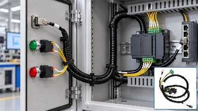
A good crimp forms stable, gas-tight contact between the strands and the terminal barrel. The troublesome part is that a poor crimp often passes a bench test and fails months later. An under-crimp leaves low contact area and weak retention. An over-crimp cuts or work-hardens strands and deforms the barrel.
Typical root causes:
A die or applicator that does not match the terminal manufacturer's specification
Worn tooling
Hand tools on production runs
No crimp-height or pull-force verification
Insulation caught in the conductor crimp, or strands outside the barrel
Prevention. Follow the terminal manufacturer's tooling and crimp-height specification. Check crimp height at setup and at defined intervals. Verify pull force on samples against the terminal supplier's minimum for each conductor size. For critical power terminals, cross-section analysis shows strand fill and compression directly. A basic continuity test cannot see a weak crimp and is not a substitute for any of these.
When evaluating a harness supplier, ask which crimp-height tolerance, pull-force criterion and sampling frequency they apply, and where those values come from.
Undersized Conductors and Missing Derating
A conductor's ampacity rating assumes specific conditions, and the inside of a cabinet often differs: higher ambient temperature, bundled conductors and restricted airflow. An undersized conductor heats along its whole length, not only at the terminal, and ages its insulation.
The design should document load current and duty cycle, conductor material and cross-section, insulation temperature rating, ambient temperature inside the enclosure, the number of grouped current-carrying conductors, and the installation method (free air, duct or bundle).
Calculate ampacity with the standard that governs your installation, for example IEC 60364-5-52 in IEC markets or the ampacity provisions of NFPA 70 (NEC) in the United States. Confirm the edition in force and any national deviations; the applicable tables and correction factors differ.
Final conductor sizing is an electrical design decision. A harness manufacturer can check that the wire list is buildable and flag conflicts, but the design owner approves the gauge. Writing the derating assumptions into the drawing notes keeps the choice visible and auditable.
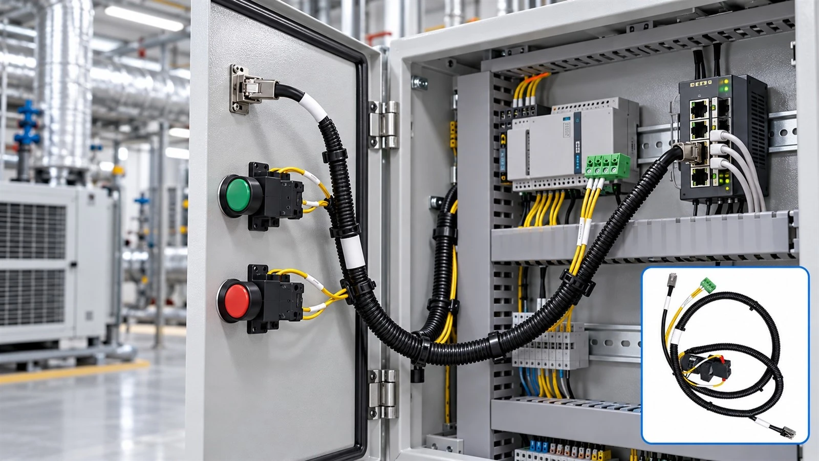
Terminal and Conductor Mismatch
A terminal can look right and still be wrong. Four common mismatches:
Size. A terminal sized for a smaller conductor cannot form a proper joint on a larger one, and the reverse leaves a loose barrel.
Geometry. Ring, fork, ferrule and pin terminals suit different equipment. A ring lug with the wrong stud hole will not seat.
Materials. Dissimilar metals in the presence of moisture can corrode.
Tooling. The right terminal crimped with the wrong die is still a wrong joint.
Prevention. Use a revision-controlled bill of materials that ties each conductor to an approved terminal part number and approved tooling, verified at first-article inspection. Substitutions should need a documented change.
|
BOM item |
Confirm |
|
Conductor |
Material, cross-section, strand construction, insulation rating |
|
Terminal |
Manufacturer, part number, approved conductor range, plating |
|
Connection type |
Ring, fork, ferrule, pin; stud or clamp dimensions |
|
Tooling |
Approved die or applicator and setting |
|
Inspection |
Dimensional and workmanship criteria |
Conductor Damage During Stripping
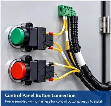
Nicked or cut strands reduce the effective cross-section at one point, which becomes a heat concentration and a fatigue site under bending and vibration. As an illustration only, cutting three strands of a 19-strand conductor removes about 16% of the strand count there, assuming equal strand diameter.
Typical defects are cut or missing strands, strip length that is too short or too long, insulation trapped under the barrel, and batch-to-batch variation from blade wear.
Prevention. Use automatic stripping with verified strip length, maintain blades, inspect the stripped conductor visually or by camera before crimping, and verify the first piece after every setup change.
Poor Routing, Mechanical Stress and Heat Exposure
Correctly sized and terminated wires can still fail early if routed badly. Cabinets contain contactors, drives, transformers and power supplies that generate heat and constrain routing.
Sharp bends near terminals stress the joint.
Without strain relief, movement and vibration go straight to the termination.
Over-tight cable ties deform insulation.
Braking resistors, drives and transformers can push insulation past its temperature limit.
Power and signal wiring routed together can interfere with sensitive circuits. That is a reliability issue, not an overheating one.
Prevention. Define routing paths, minimum bend radius, support points and separation rules at the design stage. A harness built to the cabinet layout can match branch lengths and strain-relief positions to the real path, but it must be installed as laid out.

Wrong Wiring and Unclear Identification

This cause does not generate heat. It is included because it causes costly commissioning delays and, at worst, equipment damage. Swapped phases, a control wire on the wrong terminal or a label that has rubbed off are typical, and a cabinet with dozens of similar conductors makes errors easy.
Prevention. Use unique, durable markings at both ends that match the wiring diagram, a revision-controlled wire list, and an automated circuit test against the netlist rather than a visual check. This is one of the clearest advantages of a prefabricated harness, because every circuit is checked before shipment.
Sensor Cable Assembly and Servo Motor Cable Assembly: Same Causes, Different Priorities
The seven causes also apply to the cables that leave the cabinet for the machine, but the order of importance changes with the signal or power being carried.
Sensor Cable Assembly
A sensor cable assembly carries very little current, so thermal failure is rare. The usual symptom is an intermittent or noisy signal that is easy to mistake for a faulty sensor. A marginal crimp or a connector that is not fully mated can produce exactly that. Fine-gauge conductors also make stripping damage more serious, because one cut strand removes a larger share of a thin conductor. Shield termination, routing away from power wiring and clear identification usually matter most. Check connector series and pin assignment against the sensor datasheet.
Servo Motor Cable Assembly
A servo motor cable assembly typically carries motor phase power and often feedback and brake lines in the same cable. Where the axis moves, the cable flexes thousands of times, so fatigue at the terminal exit becomes the main risk. Crimp quality , stripping damage and strain relief dominate. Shield termination at the drive and the motor also matters, because drive switching is a common noise source. Use cable rated for the motion type (fixed or continuous flex), and follow the drive and motor manufacturer's cable and connector specification, including coupling torque.
|
Assembly |
Typical symptom |
Causes that matter most |
Specify at quotation |
|
Power distribution cabinet wire harness |
Overheated terminal, intermittent shutdown |
1, 2, 3, 4, 7 |
Current, derating assumptions, terminal and torque data |
|
Sensor cable assembly |
Noisy or dropped signal |
2, 5, 6, 7 |
Connector series, pin assignment, shielding, cable length |
|
Servo motor cable assembly |
Faults after repeated motion, drive noise |
2, 5, 6 |
Flex rating, shield termination, connector type, bend radius |
The three are usually ordered as separate assemblies, but the same controls apply: a revision-controlled BOM, verified crimps and a circuit test of every connection.
How Do You Diagnose a Connection That May Be Overheating?
Follow your site's electrical safety procedures. Do not handle suspect connections while energized.
Thermographic scan under normal load
Scan the cabinet while it carries typical load; a lightly loaded joint can look normal and still be faulty. Compare like with like, such as the same joint on each phase or the same type of joint at similar load. A joint noticeably hotter than its twins is more informative than any single absolute reading. Judge absolute temperatures against the terminal and insulation ratings and the temperature-rise limits in the relevant device standard. NFPA 70B and your equipment manufacturer's documentation describe inspection practice and severity criteria. Record the load at the time of the scan.
Measure contact resistance (de-energized)
A micro-ohmmeter can measure the resistance of an individual joint. Compare against identical joints in the same cabinet and against the device manufacturer's limit, if one is published. A joint reading well above its neighbors needs attention even if it looks fine.
Inspect the joint itself
Look for discoloration, pitted contact surfaces, hardened or brittle insulation, and deformed lugs. Check whether the terminal type is the right one, and check the torque against the datasheet value. Spring-clamp and push-in terminals fail differently from screw terminals: loss of spring force and a poorly seated conductor are the usual suspects, not loosening.
Replace, then find the root cause
When the joint shows heat damage, re-tightening is not enough. Replace the terminal and the damaged conductor end, then ask which of the seven causes started the loop. Otherwise the new joint will go the same way.
How a Tested Power Distribution Cabinet Wire Harness Reduces Manufacturing-Side Failures
A power distribution cabinet wire harness built under a controlled process moves cutting, stripping, crimping, marking and testing out of the cramped enclosure and onto a jig with proper tools and lighting. Each step can then be defined, measured and recorded.
|
Failure risk |
Manufacturing control |
Intended benefit |
|
Poor crimping |
Approved tooling, crimp-height checks, pull-force sampling |
More consistent terminations |
|
Terminal mismatch |
Revision-controlled BOM, first-article inspection |
Fewer substitutions and sizing errors |
|
Stripping damage |
Automated stripping, strand inspection |
Protects conductor cross-section |
|
Wrong wiring or labels |
Controlled wire list, permanent marking, 100% circuit test |
Fewer commissioning errors |
|
Routing and mechanical stress |
Branch and strain-relief design to match the layout |
More consistent installation |
|
Production variation |
In-process and final inspection, lot records |
Repeatable batches |
These controls address the manufacturing causes, and the same approach applies to sensor cable assembly and servo motor cable assembly builds. They do not replace electrical design review, correct torqueing on site, or final cabinet testing.
For OEM production: A completed harness can reduce measuring, cutting, stripping and identification work during final assembly and make drawing revisions easier to control. The saving depends on cabinet complexity, volume and your current process.
Incoming Inspection Checklist for OEM Buyers
This applies to any supplier. Use an approved sampling plan and perform destructive tests only on designated samples.
Documentation and traceability
Does the harness match the approved part number and drawing revision?
Do wire gauges, insulation ratings, terminal and connector part numbers match the BOM?
Are test or inspection records included where required, and can the supplier identify the production lot?
Physical inspection
Are labels legible, unique and consistent at both ends?
Are terminals centered, with a small visible gap between insulation and barrel and no bare conductor outside the barrel?
Do crimp barrels look uniform, without cracks, flash or off-center seams?
Is the conductor free of visible stripping damage?
Are lengths, branch positions, sleeving and strain relief within drawing tolerance?
Electrical, mechanical and installation
Do circuits match the wiring diagram on a continuity check, and are specified insulation tests documented?
Do mating connectors and terminals fit the equipment?
After installation, were screw terminals torqued to the manufacturer's value and witness-marked?
Where required, is a re-check scheduled after the first operating period?
What to Specify When Ordering a Custom Harness
Clear documentation prevents many manufacturing errors and shortens quotation time. Provide the items below. For a sensor cable assembly or servo motor cable assembly, also state the connector series, shielding, flex requirement and cable length.
|
Area |
Information |
|
Electrical |
Voltage, current, conductor sizes, insulation rating, ambient temperature, grouping, applicable standards |
|
Wiring |
Wiring diagram, wire list, connector and terminal part numbers, pin assignments, approved lug or ferrule type |
|
Mechanical |
Dimensions, branch lengths, routing constraints, bend radius, sleeving, mounting points |
|
Quality |
Required tests, crimp and pull-force criteria, workmanship standard, reports, traceability, first-article approval |
|
Production |
Annual and per-order quantity, schedule, planned revisions, packaging |
For repeat orders, a revision-controlled specification helps later batches match the approved first article.
Frequently Asked Questions
Q: What causes terminals to overheat in distribution cabinets?
A: The underlying cause is high resistance at a connection, or a conductor that cannot dissipate its heat. Typical triggers are loose screw terminals, poor crimps, undersized or un-derated conductors, mismatched terminals and mechanical stress. Confirm the actual cause by inspection and measurement.
Q: Can a loose terminal cause intermittent power loss?
A: Yes. A connection with unstable contact can behave intermittently, especially with vibration or temperature change. Other faults can look the same, so inspect and measure before assuming it is the cause.
Q: How can I find an overheating connection in a live cabinet?
A: A thermographic scan under normal load, comparing like joints, is the usual first step. Follow your electrical safety procedures and do not touch energized parts. Confirm findings with de-energized inspection and contact-resistance measurement.
Q: How can I tell if a crimped terminal is reliable?
A: Assess it against the terminal manufacturer's specification: visual inspection, crimp height, controlled pull-force testing and, for critical joints, cross-section analysis. Continuity alone does not show mechanical or long-term quality.
Q: Should I re-torque screw terminals after commissioning?
A: Follow the terminal or device manufacturer's instructions. Some specify a re-check after an initial operating period. Use the datasheet torque and add witness marks so later movement is visible.
Q: Does a prefabricated harness prevent cabinet wiring failures?
A: It reduces errors in wire preparation, terminal selection, crimping, labeling and assembly consistency. It cannot remove failures from incorrect electrical design, poor installation or lack of maintenance.
Q: What tests should a distribution cabinet wire harness pass?
A: That depends on product and application. Circuit verification, insulation resistance, crimp inspection and pull-force testing are common, and dielectric withstand may be required. State methods, acceptance limits and sampling frequency in the purchase specification.
Q: How do I select wire gauge for a cabinet?
A: Base it on load current, conductor material, insulation rating, ambient temperature, grouping and installation method, using the standard that applies to your installation. The responsible electrical designer should approve the final choice.
Q: What does a manufacturer need to quote a custom harness?
A: A wiring diagram or sample, wire and terminal specifications, connector details, dimensions, operating conditions, test and inspection requirements and estimated quantity.
Q: Do these causes also apply to sensor and servo motor cables?
A: Yes, with different priorities. A sensor cable assembly mostly fails as an intermittent signal, so crimp quality, shield termination and routing matter most. A servo motor cable assembly adds flex fatigue and drive noise. Follow the drive, motor or sensor manufacturer's cable specification.
Custom Power Distribution Cabinet Wire Harness Manufacturing
Most distribution cabinet wiring failures start as a small rise in resistance or a conductor running too hot, then worsen through thermal cycling and vibration. Crimping, terminal matching, stripping and wire identification are decided in the harness factory. Torque, derating and routing depend on design and installation.
A tested power distribution cabinet wire harness puts the first group under controlled process and gives you records to verify it. Pair it with a clear specification, correct installation and regular thermographic inspection.
MingChing Electronics Technology Co., Ltd. confirm: has manufactured custom cables and wiring harnesses in Shenzhen since 2009 supports OEM and ODM projects for industrial equipment, electrical control systems and power distribution applications.
Send us your wiring diagram, technical requirements and estimated order quantity, and we will review conductor selection, terminal compatibility and manufacturing requirements before quoting your custom power distribution cabinet wire harness, sensor cable assembly or servo motor cable assembly.